USB was developed to allow the “hot-swapping” of devices to increase plug-and-play capabilities effectively. Devices can be attached and detached without restarting the computer or shutting off the device, allowing USB to be used for a wide range of applications. Two more valuable aspects are powering low-consumption devices with no external power source and utilizing various devices without needing manufacturer-specific, separate device drivers. At this time, most new PCs only have USB ports for connecting external devices.
A mouse, keyboard, PDAs, gamepads, joysticks, scanners, digital cameras, printers, personal media players, and flash drives can all be connected to a USB port on a computer. USB has become the de facto connecting technique for many of these gadgets. As a bridge power cable between a device and an AC adapter inserted into a wall outlet for charging, USB has become ubiquitous on other devices like tablets and video game consoles. This post will acknowledge how many wires are in a USB cable.
How Many Wires Are In A USB Cable?
A USB cable has four wire conductors, two of which are for power and two of which are for data. The data wires are usually 28 AWG, while the USB’s power wires are 20 to 28 AWG.


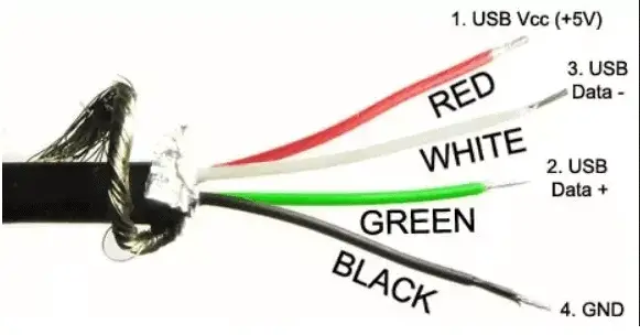
Usually, USB’s white and green wire conductors are data wires, while the red wire is a 5V power wire. The black wire is ground power wire GND.
A USB cable has two power conductors and two data conductors. The data and electricity wires are both 28 AWG. The power and data lines have been twisted, but the power cores have not. 20 AWG is the standard for powering longer wires. An A plug is found on one end of a standard cable, while a B plug is found. You can extend the maximum wire length to 5 meters using hubs and repeater extensions.
A USB port is the most popular form of USB, and the name “Universal Serial Bus” (USB) designates it. Mobile phones, computers, and game consoles typically include USB connectors. The USB connection was first designed in the mid-1990s to standardize ports for peripheral devices. Because of this change in design, printers and keyboards can now connect to a broader range of computers and hosts. Even today, there is still a wide range of USB types, but their primary function is transporting data and power. Improved transfer rates and power output have been introduced in newer models.
The geometry of the USB connection has seen radical transformations throughout the years, much like USB versions. Each new USB type often shrinks in size to accommodate new, thinner gadgets that are popular at their release. One of the most notable features of the current USB release, USB C, is that you can use it in a Thunderbolt 3 port that was not designed expressly for it. Users can use Thunderbolt 3 and USB C cables and ports interchangeably because they have the same form. However, they only work with their respective male and female USB connectors. For example, a USB port type B can only accept a USB connection type B. When determining how fast or how fast a USB cable can transfer data, it’s not about port form.
What Are the Wires Inside a USB Cable?
A USB cable contains four wires, which are Red, Black, Green, and White.
White’s first version was released in 1996. USB 1. XX is the version from which it comes. Since 2000, Black has been available on the market—version 2. XX is the current USB specification. It has a maximum speed of 480Mbps. In 2008, Blue was released as a USB 3. XX version. Five gigabits per second. The “sleep and charge” function of USB3.XX is included in the Red/Yellow version. It implies that if the host device is switched off, your gadget with this functionality will continue to deliver electricity. It is a lifesaver when charging our smartphones whenever we want.
A bare or open conductor is required on any USB cable with four wires. It usually encircles the four primary wires surrounding this open wire. Shielding is the name given to this arrangement. Shielding is required to keep out unwanted outside sounds. The most common method is to use the host and an external device as ground shields. Unfortunately, shielding is frequently eliminated in low-quality, cheaply constructed USB cables, which is unfavorable for high-quality USB connections. Data security necessitates this step to avoid data loss and hardware failures.
You can still use the latest version of anything with older versions according to backward compatibility. For example, USB A 2.0 devices can be used with USB A 3.0 ports. Older USB devices can still be connected through an adaptor to a USB C port and a host, even with the newer USB C. If the host and the peripheral have different port types, StarTech.com offers a wide selection of USB cables that you can use. It is possible to find adapters for all USB kinds, not only USB C. There are limitations to how much data can be sent when utilizing older USB versions. For example, transferring files from a 2.0 USB A hard drive to a laptop with USB A 3.0 connectors is restricted to 480Mbps.
What Is The USB Color Code?
The USB color codes are white for USB 1.0, black for USB 2.0, blue for USB 3.0, and red for USB 3.1.
Type A USB 1. x ports are typically white and can be identified by their white tint. The USB 2.0 specification was first published in January 1996, making it the industry’s venerable apex. Data transfer rates range from 1.5 Mbit/s to 12 Mbit/s, but only in one direction. Only keyboards and mice were targeted initially when it was first built. From the beginning, we supported both synchronous and asynchronous data transfers. Additionally, white USB ports have hot plug-and-play capabilities. Type B USB 2. x ports are typically black.
The USB 2.0 standard was released in 2000. It has a maximum transmission rate of 480 Mb/s and can only be used in one way. These are known as high-speed USBs. Because it is physically backward compatible with USB 1.1, you can connect USB 2. x devices to USB 1.1 and have them work just like before the change. It has all the advantages of a white USB port, so it’s popular. In comparison to the white USB port, this one is more stable.
The USB 3. x port is a newer version of the USB standard. Two variations of USB 3. x, USB 3.0 and USB 3.1 are available. Typically, a blue USB port is a USB 3.0 port introduced in 2013. As the name suggests, the USB 3.0 port is often known as a “SuperSpeed” USB port. Near the USB port on your CPU case and laptop is a double S (i.e., SS). At 5.0 Gbps, it appears to be ten times faster than USB 2.0 regarding potential throughput. Even though the hardware can deliver a maximum of 5 gigabits per second, in practice, it does not.

A few motherboards have red USB ports. A laptop or desktop computer in sleep mode, hibernation mode, or sleep mode does not give electricity to the USB 3.1 Gen 2 and USB 3.2 standard ports. However, these red-colored USB ports still get electricity when your laptop or desktop is asleep, sleeping, or hibernating. As a result, these USB ports are sometimes referred to as “Sleep and Charge Ports” or “Always Ports.”
What Do The Four Colored Wires In A USB Cable Mean?
The four colors inside a USB cable are Red, Black, Green, and White.
The red wire is the “positive” wire, indicating that the power source is on this one. This cable is essential for every USB-powered device. Cutting the red wire is a standard defusing method in action films. This wire is safe to use because the voltage is just 5 volts. DC, or direct current, is used in this 5-volt cable. Power can only flow through the red wire when the black ground wire is present. This ground wire, or negative wire, is used to complete the circuit of said electrical equipment. These red and blue lines are the USB device’s power wires.
The red and black cables are the main power lines. To communicate with a PC or other electronic device, we must first establish a method to transmit data. As a result of your work, specific data must be sent across devices. We could transport data using the white wire. However, a complete circuit necessitates the presence of an opposing white wire to balance out the data carried by the white wire. Therefore, a green wire must complete the white wire’s circuit. The DATA + is connected to the green wire, the negative data wire. Using the green cable, your data can be copied or moved from your PC or any other electronic device.
What Chargers Have Red And Black Wires?
The red wire has a positive wire of 5 volts. The black wire is an adequate ground wire.
You can join the red and black wires if they are insulated. Wire burning or circuit failure can occur if the bare copper surfaces of both cables come into contact with one another. Otherwise, the wires may need to be replaced soon because they aren’t built to last. The phases of current flow in red and black wires are distinct. Therefore, red and black wires must be linked to separate buses. Even though they’re both current, linking them would not be wise.
To avoid damaging the neutral wire, don’t connect them. Doing so can cause the voltage to rise higher than it should. However, if the correct port is used, it is possible to braid red and black air into the same box. In addition, both should be insulated. Consequently, a short circuit or even a full-blown explosion might occur. As a result, it’s best to proceed with caution. Otherwise, you risk damaging the circuit and, at the very least, interrupting the passage of electricity via the wires. Moreover, you can harm the circuit itself in the worst-case scenario.
How Do I Connect 4 Wires To 2 USB Wires?
Connect a 4-wire USB to a 2-wire USB. Remove the insulation from the ends of the 12-2 and 12-3 wires by slicing each wire in half. Next, push the wires into the electrical junction box and strip them.
Look at the 12-3 cables’ four conductors. You can connect a 12-2 wire in two ways to this cable. In the first instance, the black wire of the 12-3 cable can be used as the hot wire, which is the recommended method. Assemble the black and white wires of both cables and join them. Leave the red wire in the junction box uncapped. Please make sure all splices have plastic twist caps on them. It’s possible that the ground wire isn’t connected at all. Alternatively, the red wire can be used as the hot wire. Connect the 12-3 cable’s red wire to the 12-2 cable’s black wire. Next, connect the two white wires. Keep the 12-3 cable’s black wire capped and undisturbed in the connector box.
Connecting a four-wire electrical connection to a two-wire electrical line might be difficult without any additional information. Different voltages need different connections between the wires of a two-wire line. Electricity runs through a four-wire system that includes four hot wires (red and black), one standard wire (white), and a grounding wire (grey). The two wires that make up a two-wire line are typically white typical and black hot. Even if the ground is there, it would not be linked in some instances.
What Color Wire Is Positive?
The red wire is positive.
Secondary live cables are commonly red electrical wires. They are frequently used when installing extensive equipment like stoves, dryers, and air conditioners. A 120-volt supply line is sufficient for smaller devices, but a separate red supply wire is typically required for more critical items, necessitating a 240-volt circuit. In some 120-volt applications, red cables can also be utilized. Red and black wires can serve as switch legs.
Ceiling fans with separate motors and light switches often use red wires. As a result, one switch controls the fan motor, and the other controls the light attached to the hot red wire. Interconnected smoke alarms also employ red wires as “trigger wires.” All the linked sensors will go off simultaneously if the red wires activate one alarm. You can accomplish all of these applications with orange wire instead of red.
How to Determine Negative and Positive Wires?
Use a digital multimeter to determine the negative and positive wires. Also, a wire with both sides of the same color, commonly copper, and a strand with a grooved texture is considered the negative strand.
An extension cord’s negative wire is often ribbed. The strand with a grooved texture is indeed the negative wire if the wire is copper and has the same color on both sides. You can determine which side of the wire has the ribbing by running your fingertips down it. The other wire is pleasant to touch. The cable will be a source of power for your device. On a ceiling light fixture, locate the positive black wire. You should first find the three wires coming from the hole in the wall where you will install the light—note which wires are positive, negative, and connected to the ground. The ground wire can be copper rather than green.
The speaker wire’s copper wire is often the positive wire. Wires used for speakers and amplifiers usually include a silver strand for the negative and a copper-colored strand for the positive. It’s simple to see the polarity of these wires because transparent housing joins them together. You can find out where the negative wires are in an automobile by checking the owner’s handbook. Car fires are assigned colors according to a scheme developed specifically for each model. Find the wiring diagram for your vehicle in your owner’s handbook since there is no standard worldwide system. You can usually get a copy at a public library or online if you’ve misplaced your handbook. Ask a mechanic at a nearby shop or dealership for help as well.
Set your digital multimeter to measure direct current voltage. This sign looks like a capital “V” with just a straight line above it, and it is located on the multimeter’s selection switch, which is the vast knob in the middle of the multimeter. Your multimeter’s DC voltage setting is shown below. It would be best if you never used analog multimeters to check polarity. Analog multimeters can be damaged if the wrong leads are connected to the wrong conductors.
How to Test Black and White Wires?
You can test the black and white wires with a multimeter.
Set the voltage measurement on your multimeter. Electricity flows via a wire at a specific voltage pressure; a hot black wire conveys this voltage. Therefore, you should place the prong of the red wire of the multimeter on the bare metal at the end of one of the black wires. You can use the red wire from the multimeter to check a hot black wire, so don’t get confused. Black represents negative on a multimeter, whereas negative is characterized by red.
Touch it to an exposed wire’s end using a multimeter’s bare metal prong. Then, turn the meter on and see what it says. The black wire is hot if you obtain a reading; if you don’t, it’s cold. Repeat the test to see if the other black wire is hot. Again, the black wire is hot if you receive a reading; if you don’t, the wire isn’t hot. The USA has a stringent set of guidelines for residential wiring, which includes well-specified colors on the outside casing of the cables. All three colors are referred to as “hot,” “neutral,” or “ground.” Rewiring a light switch or plug socket can reveal two black wires occasionally. Before continuing, make sure you know that the black wire is hot. A multimeter is the most convenient and safest way to check for current.
What Do Different Color Wires Mean?
Green wires are ground wires, white and grey lines are neutral, and blue and yellow cables are hot wires.
The black electrical wires carry the power source from the power outlet. They are used in all kinds of circuits. Take care when working with them; a hot wire is recognizable by its black color. The black wire in any circuit should always be regarded as live. It is common for these wires to act as a switch leg, delivering electricity to switches and outlets in every circuit. A switch or outlet’s power supply is fed via a black wire, not ground or neutral wire. Residential structures are the most common place to find them.
Electrical wires in 220-volt circuits are frequently seen in multi-conductor cables, with red wires acting as the secondary live wires. In addition, these cables are used to link smoke detectors that are hard-wired into power supplies to switch wiring. You can connect two red wires or attach a red wire to a black wire. Red cables are regarded as “hot” because they are good conductors of electricity.
In commercial structures, blue and yellow wires are used as live wires drawn via a conduit. Although these lines carry power, they aren’t used in the conventional wiring of outlets. Instead, travelers are employed in more complex circuits and used as hot wires to transmit electricity between switches and poles. Except for three or four-way switches that use blue wires as travelers, all three-way and four-way switches use yellow wires.
Neutral wires are identified by their white or grey coloration. That implies it is connected to the neutral bus bar of an electrical panel. For example, a light bulb or an outlet draws electricity from a circuit. It returns it to the electrical panel through a neutral (commonly white) wire linked to the neutral bus bar, which feeds the power back into the utility grid. There is a distinct difference between white and grey wires regarding residential and commercial properties. Connecting one white or grey wire to another white or grey wire is the only way. However, even though they are neutral, the imbalanced load on these wires can still transport current, so they should be treated cautiously. To determine if a white wire is now operating as a hot wire, look for it to be labeled Black or red.
Are All USB 3.0 Ports Blue?
Yes, all USB 3.0 ports are blue. Blue ports on older PCs commonly identify USB 3.0.
There are three generations of USB ports. The two most significant differences are the transmission rate (speed) and the number of connection pins used by different USB versions. USB 3.0 ports contain nine pins and have a transmission rate of 5 gigabits per second, but USB 3.1 variants have a standard 10 gigabit per second transfer rate. USB-C can connect to USB 3 ports with a suitable cable or adaptor, even though it’s not a USB 3 port by design.
Blue ports on older PCs commonly identify USB 3.0, but this is not always true. It is a fact that blue ports have never been found on Macs. In its early days, people utilized USB 3 ports in conjunction with USB 2 ports. They’ve been color-coded to avoid accidentally connecting to the wrong port to make it easier to tell them apart. Color differentiation became unnecessary for many USB 2.0 ports as USB 3.0 ports replaced them. Because USB 2.0 ports are becoming less common, the need for color differentiation has diminished due to the introduction of USB. C’s
The USB-C connector is distinct from the other three USB connectors, all theme variants. Data transfer and charging speeds are improved when USB-C provides more pins. With the proper connection or adaptor, you can use it at 2.0, 3.0, 3.1, and 3.2 Mbps rates. Thunderbolt 3 compatibility, which allows connections to Thunderbolt 3 devices, is another unique feature of USB-C. If your computer supports Thunderbolt 3, you can use the USB-C connector for USB and Thunderbolt 3 connections. You’ll need a Thunderbolt 3 cable or adaptor to connect your device. Find out what musicians and engineers can expect from Thunderbolt 3 and USB-C.
What Do The Wires On A USB Mean?
The USB has four conductors: two of which are for power and two for data. The data wires are 28 AWG, and the power wires are 20–28 AWG.
USB is an abbreviation for “Universal Serial Bus”. USB cable assemblies are a common choice for connecting computers to a wide range of peripherals, like cameras, camcorders, printers, and scanners. Currently, the USB 3.0 devices that are produced are backward compatible with USB 1.1 devices. Because USB cables are “Hot Pluggable,” you can connect and unplug them without the danger of the computer stalling. The data transfer rate of USB cables can go up to 480Mbps. Compare this to serial transmission, which sends data at roughly 20Kbps. In addition to transmitting data, USB connections also provide electrical power. Therefore, it is possible for “USB powered” gadgets to recharge camera batteries and other USB peripherals.
Multiple connection types make it simple to tell which plug goes into your computer and which goes into your peripheral device. In general, USB cables are inexpensive and widely available. The backward compatibility of USB standards is one of their best features. Put another way, if you want to use USB 2.0 or USB 3.0 devices, you can do so without issue. However, to take advantage of USB 3.0’s maximum throughput, all devices and cables/connectors must comply with the newer specifications. USB 2.0’s maximum transmission speed of 480 Mbps will be the “lowest common denominator” instead.
Does Neutral Wire Have Power?
Yes, neutral wires have power. The neutral wire carries the current back to the initial power source.
A second wire must complete a circuit once the hot wire has been initiated. The neutral wire performs this function. The circuit returns to the source of electricity through the neutral wire. Instead of connecting to the ground or busbar, a neutral wire connects the circuit to the electrical panel’s ground. It permits power to flow freely through the electrical system, allowing you to get the most out of it. Your outlet will be protected from any defective or excessive current as well. There are neutral wires with white or grey casings. Although they cannot conduct electricity, they should handle them with the same care as a hot wire.
Voltage control can be achieved using a neutral wire, a current-carrying conductor. The unused power is returned to the transformer via this device, usually white. Conductor power can be alternated, and the electrical transmission circle is completed. One half of a whole circuit is neutral; the other half is hot. Only in AC alternating current power circuits are neutral wires present. Regular 240V circuit neutral wires are white, but those in industrial 480V circuits are grey.
The neutral wire is an essential part of a three-wire system, but it is not found in all North American AC power circuits. Some devices on the continent use a 208V 3-wire system with three hot wires and one ground wire. Two hot wires in the circuit carry the power, while the neutral wire is deleted. 208-volt systems are non-existent in Europe, or the circuit always includes the neutral wire. Switching between the live and hot wires in Europe’s 3-wire system is possible by spinning.
Where Do You Connect the Pink Wire?
Connect the pink wire to the black wire on the controller.
It would be best to link the white wire to the white wire. Next, connecting the controller’s black wire with a pink wire in the wall switch box to turn off the light or fan is necessary. Connecting black to Black can prevent the switch from shutting off the light. A pioneer vehicle stereo’s car speed signal input cable is colored pink. In other words, if you connect this cable to your car’s speed sensor, the Pioneer car radio will receive signal data, including speed and RPM. It uses these signals to, among other things, adjust the volume and show text alerts about low gasoline when necessary.
Kenwood vehicle stereos come standard with a pink cord for a good reason, but this isn’t true of other stereo systems. The wire’s color indicates the external amplifier control. If you use the Kenwood car radio to connect an external amplifier to your car’s sound system, the latter will handle all the necessary setups. As a result, if you have a Kenwood vehicle radio, you can use the pink wire to double its sound system’s output. The pink cable connects the left front speaker in most Toyota vehicles.
The speaker wire is pink in Ford automobiles. Ford vehicles use this color of wire to connect the left rear speaker. This wire is used for power antennas in General Motors cars. You can use your car’s antenna for this purpose. Additionally, even if the vehicle is not running, you must keep this wire connected to the radio to get the best reception. The pink wire on a Nissan vehicle radio may mean anything different depending on the model. A pink wire is typically used for the right rear speaker. An amplifier sends audio signals to a speaker through a cable like this. A Jeep’s memory input relies on the pink wire, so it’s significant. If you don’t have the wire in the vehicle’s audio system, you won’t be able to modify your speakers’ volume or fade. In addition, you won’t be able to use the sound equalization capabilities. Finally, the speakers and subwoofers won’t have high-pass crossovers.
Conclusion
“OTG” stands for USB On-the-Go, a standard that enables two USB devices to communicate. In this situation, you can use a “host” USB device to connect to a “device” USB device. For example, users can use a USB mouse as if plugged into a desktop computer with their smartphone. This interaction is possible because of a fifth pin on the USB connection.
The maximum cable length for USB 3.0 cables is 3 meters, whereas the maximum cable length for USB 2.0 cables is 5 meters. You can use an active USB extension cable to extend the signal range. The maximum cable length for USB 2.0 is 25 metres, and the maximum cable length for USB 3.0 is 18 meters. We hope you have acknowledged everything regarding how many wires are in a USB cable.


Learn more about authors in Nimblefreelancer's team biography page.
- 6 Proven Ways SaaS Founders Actually Get Customers (With Real Examples) - December 17, 2025
- Facebook Ads to Get Followers! - December 27, 2024
- ClickUp vs. Slack - December 20, 2024